Main
![]()
CMOS preamp
I promise for all of the audiofil readers of my site already noticed some disappointing noices by switching between the chanels, or noices based on the frying of the potentiometers.
With the following plan, I planned to solve this problem.
With the following plan, I planned to solve this problem.
What do I have to say, with success.
The base of this plan is:
- Switch between more inputs, without any noice
- Balance and volume controll without moving parts
- Digital powermeter
- IR remote control
- Headphone output, also with digital controll
- Low noice in- and outputs
Let’s see, what I publish from this plan.
If someone is interested, it is not impossible to remake it.
PS.: If somebody attend more to the design, will notice the very high number of the components. Please get a rise out of them, it was needed for the high quality. As a joke I called this design as "Component cemetery".
Personly the Puschbutton I would like to change to Membran Switches, but it will guide to far.
The basic idea of this was published Elektor journals between 1980 and 1989.
Switchboard
This modul takes care for the switching of different sources and the controll of the outputs.
On this modul You can find all the parts, wich takes care for the controll (switching) and with optical feedback.
The modul contains a power meter and with a small change also an IR reciver. This part You can find on a separat sheet.
On this modul You can find all the parts, wich takes care for the controll (switching) and with optical feedback.
The modul contains a power meter and with a small change also an IR reciver. This part You can find on a separat sheet.
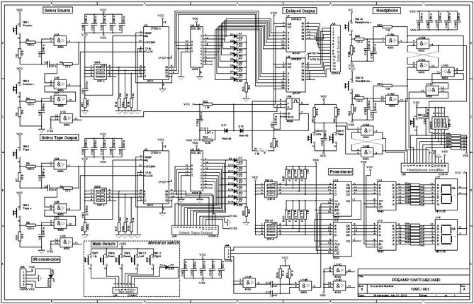
By clicking on the picture the shematic can be downloaded as PDF format, but I don't offer PCB design for.
Control board
This modul is the soul of the preamp. It contains under others the loudnes control, built with resistor scale.
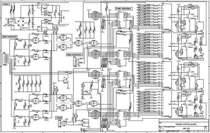
By clicking on the picture the shematic can be downloaded as PDF format, but I don't offer PCB design for.
IO board
This modul contains the In- and Outputs the preamp. This In- and Outputs are (controlled) switched from the previous discussed boards.
By the number of the components, please don't forget, this is only the left side.
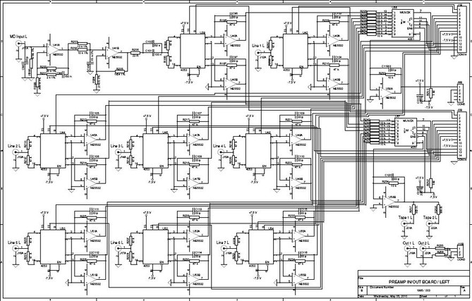
By clicking on the picture the shematic can be downloaded as PDF format, but I don't offer PCB design for.
Headphone board
This modul takes care for the headphone. You can find here also the well known resistor network as digital power regulation.
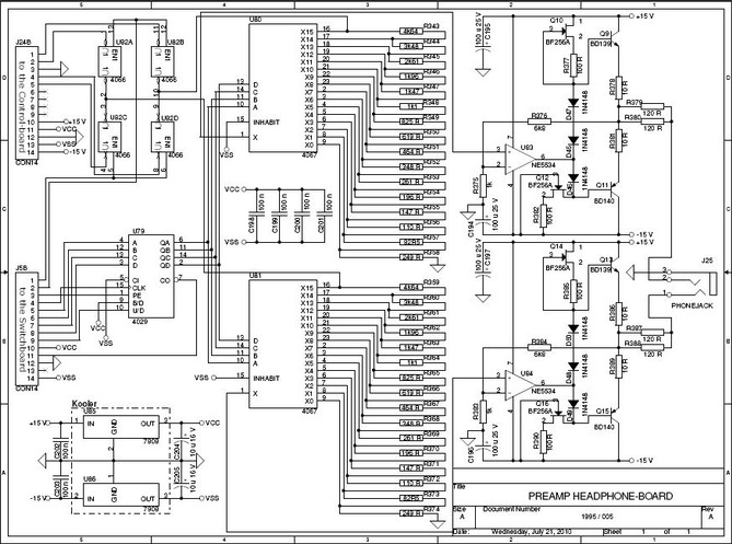
By clicking on the picture the shematic can be downloaded as PDF format, but I don't offer PCB design for.
IR reciver
So complicated electronic is today without IR remote not to find. I publish the first part the remot now.
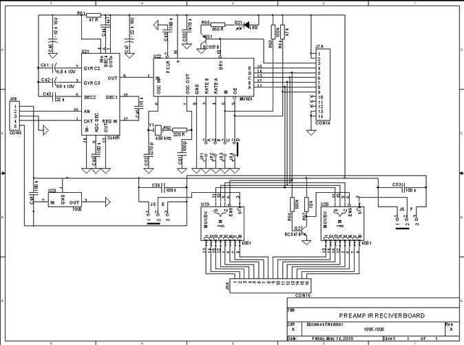
By clicking on the picture the shematic can be downloaded as PDF format, but I don't offer PCB design for.
IR sender
IR Reciver without the Sender didn't work. Here You can find the needed Sender for it.
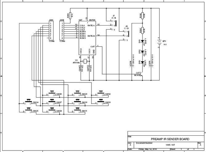
By clicking on the picture the shematic can be downloaded as PDF format, but I don't offer PCB design for.